When I was a new hardware automation engineer, one of my early assignments was to redesign an automation cart that housed multiple instruments. Every instrument arrived as a vendor model, and each one needed a carrier to bolt it into the cart. The first carrier was a satisfying little puzzle: import the vendor model, find its mounting interface, design a carrier around it, document the new parts. Then came the next instrument, and the next. The workflow never changed — only the hole patterns did — and the carrier design tasks quickly turned repetitive.
That memory is why I picked this task for the first experiment. The task: a custom aluminum mounting plate for an off-the-shelf table vise, standing in for any instrument on that cart. Entry-level and repetitive on purpose — exactly the kind of work an agentic workflow should take off an engineer's plate.
So instead of modeling it myself, I wrote a one-page workflow recipe and told Claude to execute it end to end.
The recipe
This is the entire specification I gave the agent — mounting_hardware.md, verbatim:
# Claude Workflow: Mounting Hardware

## 3rd Part Model Import
- Vendor Item Name: Table Vise
- Vendor Item Number: V33450
- Source Path: "part_2\3rd Party Models\table_vise.step"
- Destination Onshape Folder: <folder URL>

## Mounting Plate
- Purpose: Carrier for the instrument
- Material: Aluminum 6061
- Thickness: 6 mm
- Instrument Mounting Holes: As designed in the 3rd party model
- Requirements:
    - Additional margins should be reserved to drill mounting holes
      for mounting of the mounting plate to a parent assembly.
      The parent assembly is unknown yet.

## Output items
- Part: the generated mounting plate
- Assembly: mate the mounting plate to the imported equipment

## Properties
- Name any created part and assembly
- Assign item numbers
- Descriptions

## Test Pipeline
- Mounting Hole Strength safety factor is at least 1.3
Note what the recipe does not say: no plate dimensions, no hole positions, no part numbering scheme, and no folder conventions beyond one destination URL. I wanted to see which of those gaps the agent fills well — and where its defaults diverge from mine.
What happened
The run needed me exactly once. My original vendor file was a SolidWorks assembly (.SLDASM), and Claude hit two dead ends trying to import it: Onshape rejected the standalone file, then rejected a zipped version, because a .SLDASM references part geometry but does not contain it. Claude diagnosed the problem correctly, reported back, and I handed it table_vise.step instead. From that STEP file through the final strength report, the agent ran the entire recipe without me touching the mouse or keyboard.
Here is what that pass produced:
- Import: the STEP translated into an assembly and a part studio containing the vise's six bodies, all in the folder named by the recipe.
- Geometry interrogation: rather than eyeballing dimensions, Claude wrote throwaway FeatureScript queries against the imported solids — first using bounding boxes to identify the base casting, then scanning the base for vertical cylindrical faces. The result: four Ø11 thru-holes on a 190 × 185 mm pattern through the base flange. Every plate dimension came from those measurements.
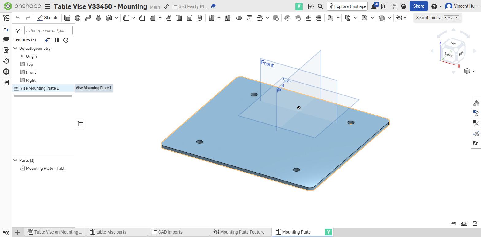
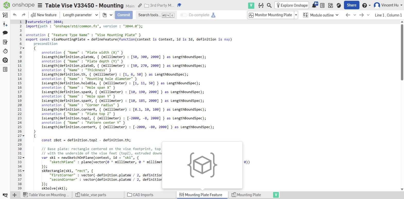
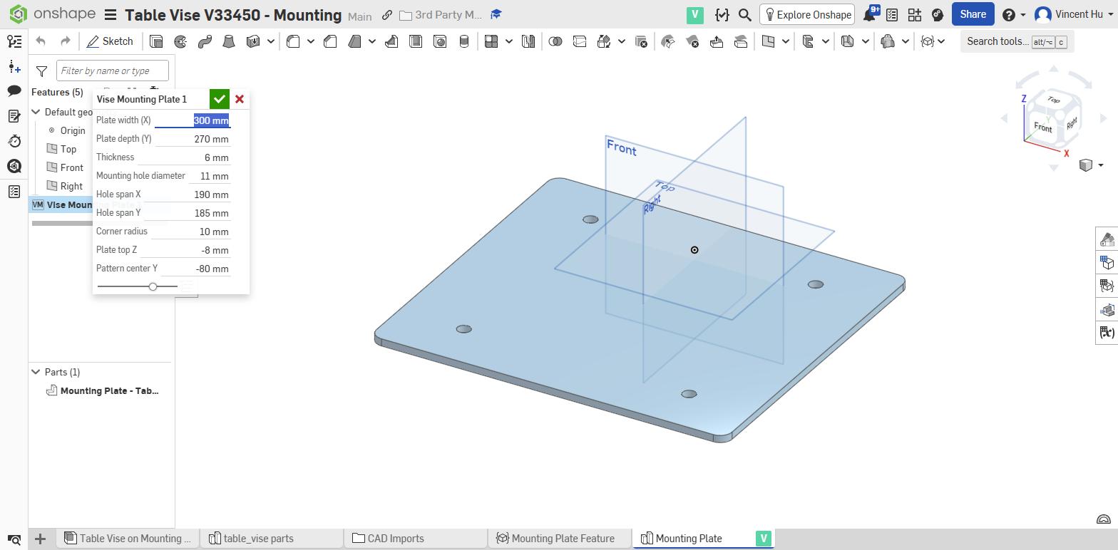
- The plate: a 300 × 270 × 6 mm AL 6061 plate with matching holes, rounded corners, and a 25 mm perimeter margin reserved for the future parent-assembly holes requested by the recipe — built as a parametric FeatureScript custom feature and tested in a sandbox before anything touched the document.
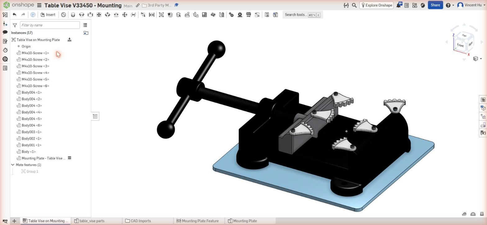
- Assembly: the plate was modeled in the vise's own coordinate system, so it dropped into the assembly with an identity transform, already seated beneath the feet. Claude then selected all seventeen instances in the UI, applied a Group mate, and fixed the plate to ground the assembly.
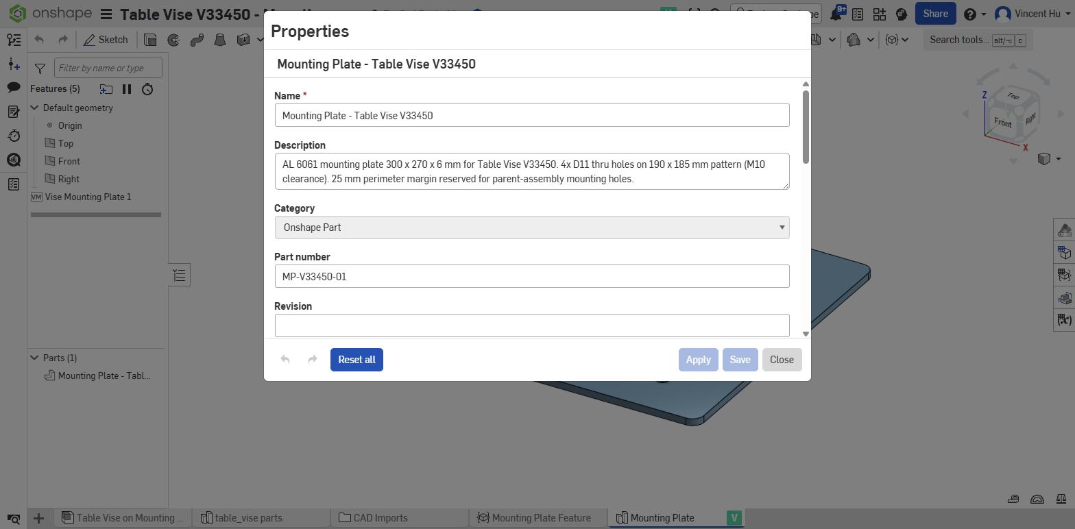
- Bookkeeping: Claude named the part "Mounting Plate - Table Vise V33450" and gave it item number MP-V33450-01, renamed and numbered the assembly (ASM-V33450-01), and filled in descriptions, material, and density through Onshape's metadata API.
- Test pipeline: Onshape Simulation isn't available on the education tier, so Claude did what an engineer without a simulation seat would do: a classical bolted-joint hand calculation covering bearing, tear-out, pull-through, bolt shear and tension for four M10 class 8.8 fasteners under a conservative bench-use load envelope. The governing mode was bearing at the hole, with a safety factor ≈ 44 against the required 1.3, documented in a markdown report with formulas and assumptions.
Two channels: Onshape MCP and Claude in Chrome
The most instructive part of this experiment is how the work split across tools. Claude had two ways into Onshape, and they were not interchangeable.
The Onshape MCP server (PTC's fs-mcp labs app) exposes exactly one discipline: FeatureScript. After OAuth, the agent gets tools to test FeatureScript snippets in a sandbox, test full custom features, create feature studios, and write code into them — and nothing else. There is no import endpoint, no assembly tooling, and no metadata access.
Claude in Chrome became the everything-else channel. Using my logged-in browser session, the agent uploaded the STEP file through Onshape's hidden file input, drove the import dialog, called Onshape's REST API directly from the page for element enumeration, part insertion, and metadata writes, clicked through the assembly UI to create the Group mate, and took screenshots to visually verify each stage.
I did not design this split. The MCP server offers nothing beyond FeatureScript, so the agent had to decide, task by task, which channel could do the job. The division of labor it settled on is telling.
The MCP channel got the engineering core. Before any code touched my document, the agent ran it in a sandbox and checked the result: one solid produced? Bounding box the right size? Exactly four hole faces? Only after those checks passed did the feature get written into the real model. That made iteration fast, because nothing could break anything.
The browser channel got the bureaucracy. Uploading files, driving the import dialog, calling Onshape's web API, clicking through the assembly toolbar — the unglamorous work of operating a web application. This turned out to be the messier half: some API calls need extra security headers, some only accept a specific version of the endpoint, and one toolbar button was mislabeled under the hood. The agent worked around each of these — at one point hovering over a button and reading its tooltip to confirm what it actually was before clicking.
FeatureScript deserves its own aside. Onshape made its modeling language something you can write, run, and test like real code — and that is what makes this workflow clean. The plate isn't a recording of UI clicks; it's a program that was tested before it shipped. My VBA macros from Part 1 never had that luxury.
What went well
One pass, end to end. After the STEP handoff, I never intervened. Import, measure, design, assemble, document, verify: this was a genuinely end-to-end AI workflow — the thing Part 1 argued should exist.
Semantic understanding of the mounting interface. Claude found four cylinders and understood what they were: the vise's mounting holes. It also understood that "Instrument Mounting Holes: As designed in the 3rd party model" meant the plate had to match them — position for position, on the measured 190 × 185 mm pattern. One sentence of intent in the recipe became fully anchored geometry.
All bookkeeping automated. Names, item numbers, descriptions, material — the metadata entry that Part 1 called the invisible time sink happened as a matter of course. Some of it was stamped by the custom feature itself, so it survives resizing; the rest was written through the metadata API.
A sensible fallback on the test pipeline. The recipe demanded a safety factor, but the subscription tier has no simulation. Instead of failing the step or inventing a simulation result, Claude fell back to an analytical method and showed its work. That's the judgment call I'd want from a junior engineer in the same situation.
What could be improved
All three of my complaints share the same root cause — and it is the thesis of this series showing up earlier than expected.
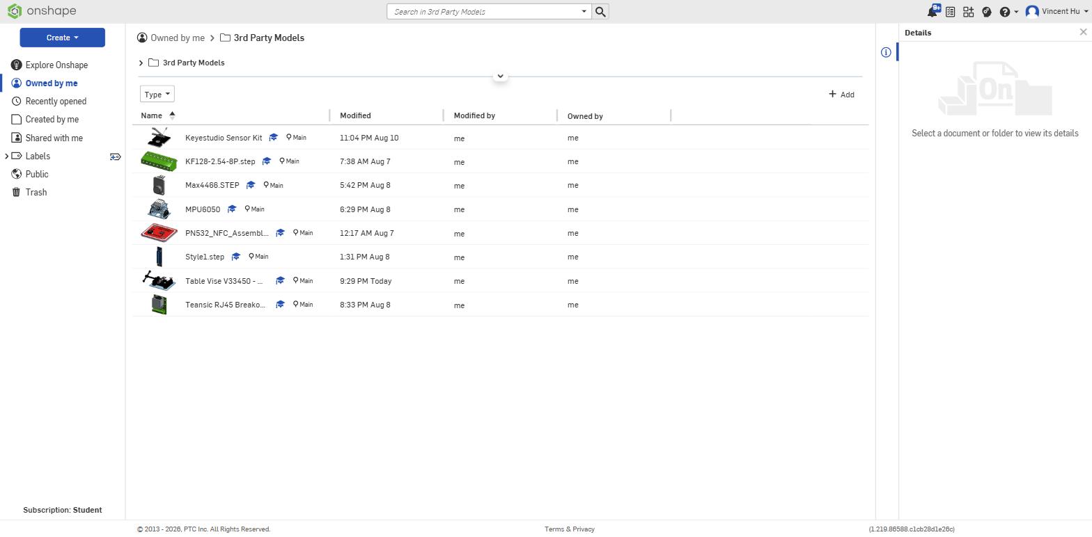
The plate lives in the wrong document. Claude built the mounting plate, its feature studio, and the assembly inside the imported vendor document, which sits in my "3rd Party Models" folder. My convention is the opposite: vendor models stay pristine in their library, while custom designs live in a separate folder and their own document, importing the vendor model only into a parent assembly. The result is a third-party library document that is half vendor data and half my IP. But the recipe never told Claude otherwise.
Drilled holes where I wanted threads. The plate's instrument mounting holes came out as Ø11 drilled clearance holes — mirroring the vise's own — with M10 bolts and nyloc nuts recommended underneath. On my bench, I'd tap the plate M10 so the vise can bolt down without loose hardware below. Again: the recipe never specified that.
Parametric, but not configurable. Every dimension of the plate is programmed into the custom feature, and the feature exposes nine editable parameters. But Claude never made the judgment call a CAD lead would make: deciding which parameters should be promoted to document variables or a configuration so the next engineer can resize the plate without reading FeatureScript.
None of these are capability failures. The agent did what the recipe said, and where the recipe was silent, it made defensible choices — choices that happened to violate conventions living only in my head. That is exactly the argument from Part 1: the durable value of an agentic workflow is the enforcement of guiding principles, and principles the agent was never given cannot be enforced. Document organization, thread standards, configurability rules — those belong in the recipe, or better yet, in a standing conventions file that every recipe inherits.
The recipe is already getting longer.
The tally
| Human interventions after the STEP handoff | 0 |
| Plate | 300 × 270 × 6 mm, AL 6061, 1.305 kg |
| Hole pattern (measured from vendor model) | 4× Ø11 on 190 × 185 mm |
| Item numbers assigned | MP-V33450-01, ASM-V33450-01 |
| Mounting hole safety factor (required ≥ 1.3) | ≈ 44, analytical |
| Recipe lines that produced conventions violations | the lines I never wrote |
Stay tuned for Part 2B, where I fold these lessons back into the recipe and re-attempt the end-to-end workflow.
Table vise CAD model: Precision Bench Vise Assembly via the GrabCAD Community Library.