In Part 2A, I gave Claude a one-page procedure for building an aluminum carrier plate for a commercial bench vise in Onshape. Claude completed the model in one pass, but the result violated three of my engineering conventions. Part 2B began with a simple objective: make those conventions explicit, update the procedure, and repeat the build.
The revised procedure produced the correct result, but the run took 45 minutes and 37 seconds. A review of the recording showed that the delay was highly concentrated: one assembly mate accounted for more than half of the total time because Claude had to construct it through the graphical interface. Keyboard shortcuts reduced some routine interface overhead, but they did not address the underlying bottleneck. The effective solution was to define the mate connectors in FeatureScript, where they could be created deterministically in code. With that change, the same build completed in 10 minutes and 32 seconds without corrections. This article explains why the mate was so expensive and how the workflow was redesigned around it.
Part 2A exposed three undocumented design conventions
The problems in Part 2A were not failures of CAD capability. They were specification failures: three important conventions were never included in the instructions.
First, Claude created the plate and assembly inside the imported vendor document in my third-party model library. My standard practice is to keep vendor models unchanged and create custom parts in a separate design document.
Second, the instrument mounting holes were modeled as Ø11 clearance holes matching the vise, which required bolts and nuts beneath the plate. The intended design uses M10 tapped holes so the vise can be fastened directly to the plate without loose hardware underneath.
Third, the plate was parametric but not readily configurable. The custom feature contained all nine dimensions, but none were exposed as document variables. Resizing the plate would therefore require the next engineer to inspect and modify FeatureScript rather than edit clearly named values in the feature tree.
Claude made reasonable choices given an incomplete specification. For Part 2B, I updated the procedure to remove that ambiguity: custom parts must be created in a separate document; mounting holes must use Onshape's native metric tapped-hole feature; critical dimensions must appear as Variable features in the feature tree; and a requested "mate" must be implemented as an actual Onshape mate, not a Group. A Group preserves the relative positions of instances, but it does not define a mechanical relationship between them.
These conventions now sit at the top of the procedure (instrument_carrier.md) as explicit preconditions:
## 1. Preconditions

- All 3rd-party models live in the designated Onshape folder.
- All newly created parts and assemblies live in a separate
  document, segregated from the 3rd-party model folder.
- All mounting holes default to metric dimensioning unless
  otherwise specified.
- Critical dimensions are parameterized as Variable features in
  the feature tree, not hardcoded in the FeatureScript.
- "Mate" in any instruction means coupling two entities with
  Onshape's native mating features (Fastened, Revolute, …).
  Group is not a mate.
- Mate type and mated entities follow how the components are
  physically joined: screws into threaded holes → mate the holes.
- Prioritize the MCP for feature creation over Claude-in-Chrome;
  use the browser only for what the MCP cannot do (import,
  assemblies, mates, properties).
The corrected workflow worked, but required forty-five minutes
I then repeated the complete procedure from a clean start and recorded the run as Take 2. The revised instructions resolved every issue from Part 2A. The STEP file was imported into a dedicated vendor document, while the plate was created in a separate carrier document. Seven feature-tree variables controlled the geometry, the four mounting holes were native M10×1.5 tapped holes, and a Fastened hole-to-hole mate joined the vise to the plate. The workflow also assigned part numbers and verified internal-thread pull-out strength in the 6 mm aluminum plate, producing a safety factor of approximately 2.0. The final model was correct.
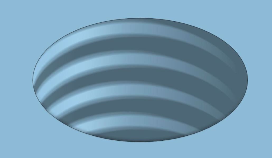
A mounting hole in the corrected plate. The M10×1.5 thread is modeled inside the bore, not the plain Ø11 clearance hole of Part 2A.
The unexpected result was the execution cost: 45 minutes and 37 seconds and approximately 111,000 tokens. More importantly, the delay was not distributed across the workflow. It was dominated by a single operation.
A single assembly mate consumed 52% of Take 2 and became the primary target for optimization.
One manually constructed mate consumed half of the run
Understanding the delay requires a clear view of how the workflow is divided among Onshape's automation interfaces. This division is imposed by the capabilities of the tools rather than by preference.
The Onshape MCP server exposes FeatureScript, which can create and test Part Studio features such as solids, holes, and geometry queries. It cannot manage document-level or assembly-level objects. Imports, documents, versions, tree variables, assembly instances, and metadata therefore use REST calls issued from the authenticated browser session. Mates are assembly features and cannot be created with FeatureScript, so in this workflow they must be constructed through the assembly interface.
| Task | Channel |
|---|---|
| Write and test FeatureScript, build the plate and its holes | Onshape MCP |
| Import, documents, versions, variables, instances, metadata | Browser REST |
| Mates, Fix, visual checks | Browser UI |
The browser interface is the most expensive channel. In Take 2, the hole-to-hole mate consumed 52 percent of the total run for reasons largely unrelated to engineering analysis:
- Claude had to construct the mate manually in the assembly. This required hiding and showing components, orienting the model to a bottom view, and selecting the correct hole edge by screen coordinates while the components overlapped.
- The operation required two corrections. The first connector was placed on a hole obscured by another body and had to be recreated. The initial +16 mm offset also moved the vise into the plate; changing the offset to −16 mm seated it correctly.
- Coordinate-based interaction is inherently fragile. Click locations change with window size, one toolbar control has an incorrect internal label, and open dialogs can obscure the feature-tree rows needed for the next action.
The bottleneck was therefore not geometric reasoning. Claude determined the required relationship quickly; most of the time was spent translating that relationship into a sequence of fragile interface actions.
Keyboard shortcuts reduced interface overhead but did not remove the bottleneck
Before redesigning the mate, I tested a lower-cost improvement: replacing mouse-driven commands with keyboard shortcuts. Much of Take 2's routine overhead came from locating controls on screen. If the recorded window size differed from the window used to establish the skill's coordinates, Claude had to recalculate each click location from a new screenshot. Unlabeled toolbar icons also required hover actions to reveal their tooltips. A shortcut avoids these steps because it invokes the command directly, independent of window geometry. I therefore had Claude configure Onshape's shortcuts and revise the workflow to prefer keyboard input over mouse clicks.
Onshape stores shortcut assignments at the account level, so Claude configured them through the browser settings page. The work proceeded in two passes. The first assigned 36 mnemonic shortcuts to commands used frequently in this workflow. The second assigned the remaining commands for complete coverage. In total, Claude configured 259 commands across six tabs without conflicts.
Claude assigns Onshape keyboard shortcuts through the account settings page. Because the shortcut map is account-specific, it must be read and updated in the active browser session.
Take 3 confirmed that shortcuts improved routine operations. shift+g creates a Group, m opens the Mate dialog, shift+6 selects the bottom view, and alt+] expands an instance to expose its named connector. Each shortcut was printed in the terminal before execution so the otherwise invisible keystroke would be visible in the recording. Excluding the mate, execution time fell from slightly more than twenty minutes to approximately nine.
The shortcuts were only one contributor to that improvement. Two other conditions also changed in Take 3: the click coordinates were correct, and Claude captured far fewer screenshots. The execution log indicates that those changes accounted for a larger share of the reduced routine overhead. More importantly, shortcuts did not simplify the mate itself. They could open the command faster, but they could not identify an obscured hole or determine the correct offset direction. Configuring all 259 commands provided a complete shortcut map, but this workflow uses only about twenty of them. Full coverage improved consistency; it was not the primary performance lever.
The mate required a structural change rather than a faster method of issuing the same commands.
Defining mate connectors in FeatureScript reduced the assembly work to one dialog
A Fastened mate requires one mate connector on each component. In Take 2, both connectors were created manually in the assembly, which introduced the view manipulation, feature selection, and offset correction described above. Fundamentally, however, a mate connector is a coordinate frame attached to a body. FeatureScript can define that frame directly with opMateConnector. I therefore moved connector creation from the assembly into the two Part Studios.
For the vise, a small custom feature calls opMateConnector on the base casting at the mounting hole. For the plate, the existing plate-generation feature creates a connector at the corresponding hole. Both connectors use the same frame convention: the origin is at the hole center, the Z-axis points upward, and the X-axis follows the global +X direction. Because the frames are defined consistently, the components align as soon as they are inserted into the assembly. No offset calculation, orientation flip, or bottom-view selection is required. The remaining assembly work is reduced to one Mate dialog and one Fix operation.
In the procedure, the same idea is three steps: define each connector in its Part Studio, then mate the two named connectors in the assembly.
### 3.1 Import the 3rd-party model
5. Add the instrument's mate connector in its Part Studio, via
   FeatureScript (no UI): a small feature calls opMateConnector
   on the base casting at the mounting hole, inserted into the
   vendor Part Studio via REST. Frame convention for every
   connector: origin at the hole center on the mounting plane
   (the base underside, Z = −8), zAxis = +Z, xAxis = +X.

### 3.4 Parameterize and build the plate
2. The plate feature also creates its mate connector with
   opMateConnector at the same hole, on the identical frame as
   3.1.5 (origin at the hole center on the plate top; zAxis = +Z,
   xAxis = +X), and names it "MC hole A".

### 3.5 Build the carrier assembly
2. Fastened mate between the plate's and the instrument's
   part-level connectors, both created in the Part Studios
   (3.1.5, 3.4.2). Remaining UI: m → Mate, select the two
   connectors (alt+] to expand each instance to its named
   connector), Enter; then Fix the plate instance.
I recorded this revised workflow as Take 3, shown in the video at the beginning of the article.
Take 2 creates both connectors in the assembly and requires two corrections. Take 3 defines the connectors in the Part Studios using a common frame convention, reducing the assembly sequence to insert, mate, and fix.
This change removes geometric definition from the assembly workflow. Alignment is specified and tested in FeatureScript, while the assembly consumes two predefined coordinate frames. Instead of constructing two connectors and resolving their offsets through the interface, Claude only selects two named connectors. The remaining assembly-interface operations are Group, Fix, and a single Mate.
One limitation remains: I have not yet tested mate creation through the REST API. The expected implementation is a BTMMate-64 feature containing a mateConnectorsQuery that references the two predefined connectors. If that approach works, mate creation can also be removed from the interface. Until it is validated in a scratch assembly, Mate and Fix remain the final UI-dependent operations.
The REST implementation also exposed a specific failure mode. Inserting a custom feature with an empty parameters array does not apply the feature's default values. As a result, the length preconditions fail and the feature enters an error state without a useful message. The solution is to include every parameter explicitly in the insert request. This issue caused one failed insertion and is now documented in the skill.
The improvement came from workflow design, not a more capable model
The three runs are compared below. Part 2A tracked human intervention but was not instrumented for execution time or token usage, so those values are unavailable.
| Metric | Part 2A | Take 2 (2B) | Take 3 (2B) |
|---|---|---|---|
| Human interventions after the STEP handoff | 0 | 0 | 0 |
| Wall clock, recorded | not instrumented | 45:37 | 10:32 |
| Tokens | not instrumented | ~111 K | ~64 K |
| Mate share of the take | n/a | 52 % | 9 % |
| On-camera mate corrections | n/a | 2 | 0 |
| Custom design document | inside vendor doc | separate doc | separate doc |
| Instrument mounting holes | Ø11 drilled | native M10 tapped | native M10 tapped |
| Configurability | 9 params, no variables | 7 tree variables | 7 tree variables |
| Joint | assembly mate, at the origin | Fastened, hole-to-hole (UI-built connectors) | Fastened, hole-to-hole (FeatureScript connectors) |
| Assembly-UI actions | n/a | Group, Fix, connectors, offset, sign, flip, Fasten | Group, Fix, one Mate |
The transition from Part 2A to Part 2B corrected the specification: separate documents, tapped holes, exposed variables, and a true assembly mate. The transition from Take 2 to Take 3 improved efficiency. Claude did not become better at constructing the mate through the interface; the workflow eliminated most of that interface work by moving connector definition into code.
Effective CAD automation assigns each operation to the right interface
Neither improvement depended on a more capable model. The optimization came from identifying the dominant operation and moving it to the interface best suited to execute it. The method is straightforward: record the workflow, measure where time is spent, identify the primary bottleneck, assign that work to the most deterministic automation channel available, and repeat the measurement. This is conventional process optimization applied to agent-driven CAD.
The resulting interface-selection rule can be summarized as a short decision tree.
Interface selection by task: Part Studio geometry goes to FeatureScript, document operations go to REST, and any remaining assembly commands use keyboard shortcuts before mouse input.
Claude Code is most effective when CAD operations can be expressed as deterministic Part Studio features. The plate, tapped holes, and mate connectors therefore belong in FeatureScript, where Claude can write the implementation, test it in a sandbox, and deploy it only after validation. Document-level operations, including imports, versions, variables, and metadata, are not available through FeatureScript and instead use REST. Assembly features remain the least automated category. When an operation such as a mate must still be performed through the interface, keyboard shortcuts should be preferred because they are independent of window size and do not require visual search. Mouse input should be reserved for selections that cannot be addressed through code, an API, or a command shortcut.
Both improvements are now documented in the two files used to initialize the next carrier workflow. This converts the lessons from a single successful run into repeatable process knowledge:
| In the workflow | Before (Take 2) | After (Take 3) |
|---|---|---|
| Mate connectors | picked on holes in the assembly | opMateConnector in the Part Studios (recipe §3.1.5, §3.4.2) |
| The mate | hide/show, bottom-view hunt, offset sign, flip | alt+], m → Mate, two named connectors (§3.5.2) |
| UI steps in the skill | click coordinates for a fixed window | keyboard shortcuts first, a verified click only as fallback |
| Finding a hidden tool | search-tools route (alt+c) |
the direct shortcut |
Mate creation is now the only substantive operation that still depends on the interface. The next experiment is to create the mate through REST using the connectors' deterministic IDs. If successful, the assembly process will become fully scripted and the interface will serve only for visual verification.
Table vise CAD model: Precision Bench Vise Assembly via the GrabCAD Community Library.