A drawer slide is a mechanism: five pieces that move relative to one another and stop where the metal makes contact. A STEP file preserves the shapes but forgets the mechanism. What arrives is fifteen bodies frozen at full extension, with names such as Mirror3 and Boss-Extrude9 and no indication of which bodies move together.
This slide is one building block in a larger project: a multi-tier cabinet that stores lab instruments vertically while keeping each one accessible on a pull-out tray. Before designing the cabinet, I needed a slide pair that behaved like the physical hardware rather than merely looking like it.
This chapter starts with a McMaster-Carr 15765A28 full-extension slide and uses Claude Code to turn the vendor STEP file into a working left-and-right pair with defined travel. It took two recorded attempts. The first ran for 38 minutes and failed my review: the model looked convincing, but each stage over-travelled by roughly five millimetres. I wrote every failure back into the workflow files and replayed the build. The second take finished in 16 minutes 26 seconds with no feature errors, no mate errors, and only two Onshape MCP API calls instead of 33. The video above shows that second take.
The difference between the two takes comes down to one rule: a stop is a pair of faces, never a bounding box.
Everything used in this run
| Component | What it is |
|---|---|
| Claude Code | The agent driving everything; terminal on the right half of the recording |
| Claude in Chrome | Browser extension: Onshape REST calls from my logged-in session, plus the few UI-only steps |
| Onshape (Student) | The CAD system; one document per vendor item |
| Onshape FeatureScript MCP | PTC's labs app: author, sandbox-test, and ship FeatureScript. Nothing else — no imports, assemblies, or metadata |
| Vendor model | McMaster-Carr 15765A28 hold-closed base-mount slide, 660 mm, STEP |
| Workflow recipe | sliding_drawer_cabinet_workflow.md: the use-case rules and step order this run replayed |
| Skill | onshape-cad-workflow: the REST payloads, FeatureScript patterns, and UI pitfalls every run inherits |
| Feature code | part_3/features/orient-import.fs, slide-members.fs, slide-connectors.fs, slide-stop-connectors.fs |
The interface-selection rule from Part 2B still applies: FeatureScript and the MCP handle Part Studio geometry; REST handles document and assembly operations; and the browser is reserved for steps that neither interface supports cleanly. In this take, the MCP delivered four custom features, REST handled everything else, and the UI was needed only three times: Import, Fix, and Mirror.
A STEP file preserves geometry, not mechanism
The import arrives as fifteen loose solids, lying on their side in the vendor's coordinate system and carrying names inherited from someone else's feature tree. Nothing in the file says, “These three bodies form the cabinet rail,” or, “The drawer stops here.” That mechanical meaning has to be recovered from the geometry itself.
Four custom features restore that meaning. They were written and compile-tested before the recording, then delivered as one Feature Studio in a single MCP call:
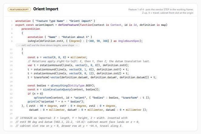
Orient Import rotates the model so Z points up, X follows the direction of travel, and the cabinet rail's front mounting slot sits at the origin. Every downstream measurement uses this frame, making the remaining features predictable and reusable.

Slide Members converts fifteen anonymous bodies into five closed composite parts using geometry alone. Long bodies seed the members; seeds with at least 90 percent overlap in X merge, joining a rail shell to its liner; and each short body joins the smallest member box that contains it. The resulting order is cabinet rail, cage A, intermediate rail, cage B, and drawer rail.
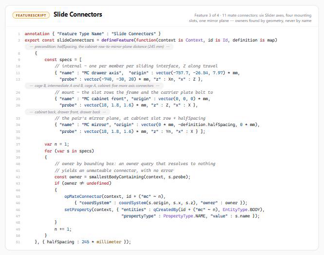
Slide Connectors places eleven mate connectors: six on the motion axes for the Slider mates, four on the mounting-slot rows, and one on the pair's mirror plane. A bounding-box probe identifies each owner without relying on names. If an owner query returns nothing, Onshape creates a connector that appears valid but cannot be mated.
The fourth feature contains the lesson that made this chapter worth writing.
A stop is a pair of touching faces, never a bounding box
My first version of the stop connectors did what initially seemed reasonable: it placed a connector at each end of every member's bounding box, along the box centreline. The feature compiled, the mates solved, and the model was still wrong. The drawer over-travelled by about five millimetres at every stage. One stop even required a limit of “−1.41 mm” to solve—a clear warning, because every limit in this pattern should be zero.
My review was straightforward: the travel limits were wrong, so I went back to the hand-built reference. That model used fourteen mate connectors placed one face at a time and eight Parallel mates. None of those connectors sat on a bounding-box extreme. They sat on the faces that physically touch: the outside faces of each ball cage's end-stop blocks, the rail lips that catch those blocks, the drawer rail's front stop tab, the cabinet rail's front tab, and the stop body at the back. Several of those faces sit about five millimetres inside the member's bounding box. The box describes the overall geometry; it does not tell you where the metal makes contact.
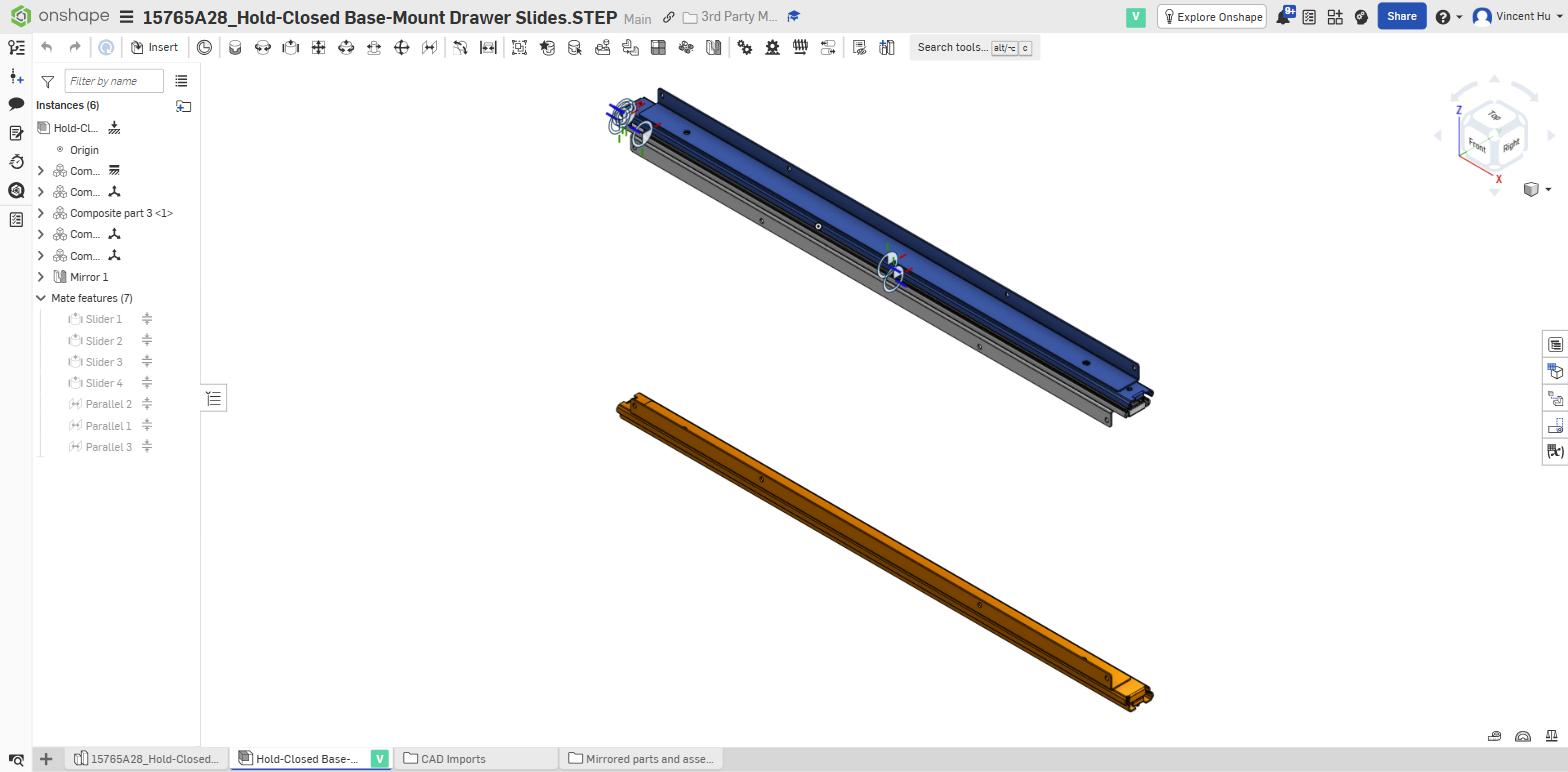
The reference model, built by hand after Take 4. Every connector sits at the centre of a physical stop face. Claude Code had to reproduce this set from geometry; its first bounding-box-based attempt missed every face by several millimetres.
The corrected feature searches for the contacting faces instead of inferring them from the overall envelope:
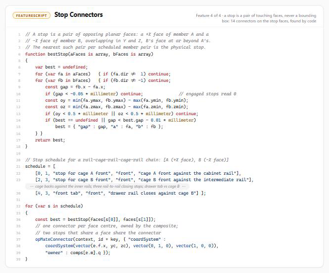
Stop Connectors examines each pair of members that stop against one another. bestStop searches for a +X-facing surface on one member and a −X-facing surface on the other, requires overlap in Y and Z, and keeps the nearest pair. That pair defines a physical stop. The feature places one connector at the centre of each face and assigns it to the composite; stops that share a face also share a connector. The fourteen generated connectors match my hand-placed reference within 0.01 mm.
The geometry provides its own validation. The STEP file is modelled at full extension, so all four extension stops should read exactly zero as soon as the mates are created: the cages are already touching their rail lips. In Take 6, they did—0, 0, 0, 0. The four closing stops read 373.1, 359.8, 735.0, and 361.2 millimetres, representing the remaining travel for each member. If a stop requires a different value, its connector is on the wrong face.
The five-millimetre error in one image: the drawer rail's stop tab sits inside its bounding box. A connector on the box corner therefore lets the model travel beyond the point where the physical hardware has already stopped.
The travel lives in eight one-sided mates, and every limit is zero
Once the connectors are on the correct faces, the mate structure becomes almost boring—which is exactly what I wanted. The four Slider mates define only the motion axes; their internal limits remain disabled. Eight Parallel mates control the travel, each joining two stop-face connectors with one constraint: a minimum Z distance of zero. Each mate reads like a statement about the hardware: cage A front against the cabinet rail; drawer rail closes against cage B. The limit is always zero because the geometry already contains the distance.
| Stop | Value at full extension |
|---|---|
| Cage A front against the cabinet rail | 0 (engaged) |
| Cage B front against the intermediate rail | 0 (engaged) |
| Cage A back against the intermediate rail | 0 (engaged) |
| Cage B back against the drawer rail | 0 (engaged) |
| Intermediate rail closes against the cabinet rail | 373.1 mm to go |
| Drawer rail closes against the intermediate rail | 359.8 mm to go |
| Drawer rail closes against the cabinet rail | 735.0 mm to go |
| Drawer rail closes against cage B | 361.2 mm to go |
Creating these mates through REST exposes a subtle trap that consumed much of the first take. Onshape returns an open limit side as isNull: false with a nullValue of “No minimum.” If that object is posted back unchanged, the open side becomes a closed zero. All six axes become pinned, and every stop fails with “Mate overdefines the assembly.” All twelve mates turned red in Take 5 before I found the cause.
The fix is to send every open side as isNull: true during creation and every later edit. This matters because suppressing or unsuppressing a mate round-trips the JSON and can pin the mate again. In Take 6, Claude Code created the stops first and the Slider mates second. All twelve solved on the first pass, and the assembly remained in its imported pose.
The proof came from the API refusing a hundredth of a millimetre
Plan A was to demonstrate the travel through the interface: right-click a stop, choose Apply limit position, and select minimum Z. The same command had worked the day before. During the recording, however, the submenu ignored every click, and the keyboard arrow eventually reached the viewport and rotated the model instead. After four attempts, Claude Code followed a rule in the workflow: when an interaction repeatedly fails, change the method instead of continuing to click.
Plan B produced a stronger demonstration. Claude Code moved the members through the occurrence-transform API in the order permitted by the stops. First, it moved the intermediate rail, cage B, and drawer together by 373.05 mm until the intermediate rail reached the cabinet's back stop. It then moved cage B and the drawer by 359.5 mm, leaving the drawer tab 0.3 mm from the intermediate rail's front end.
Two rejected commands provided the most convincing evidence. Onshape refused to move the drawer alone because one member of a mated chain cannot move independently. It also refused a 359.79 mm group move against a stop that read 359.79 mm because the request crossed the solver's tolerance by one hundredth of a millimetre. The pair closed after 732.6 mm of drawer travel, just short of the tab—exactly where the physical slide stops. Reversing the same two moves returned it to full extension without changing any of the eight stop values.
The final steps created the opposite-hand slide. The assembly Mirror feature used the MC mirror connector that Slide Connectors had placed at half the desired pair spacing. That keeps the spacing as a Part Studio parameter instead of an assembly measurement. Onshape derived the asymmetric members automatically and simply transformed the symmetric ball cage.
Claude Code then added the metadata and created V1: the McMaster part number, vendor, and a BOM flag that tells a parent assembly to count the slide as one purchased item rather than fifteen bodies. V1 becomes the stable reference for the cabinet in Part 3B.
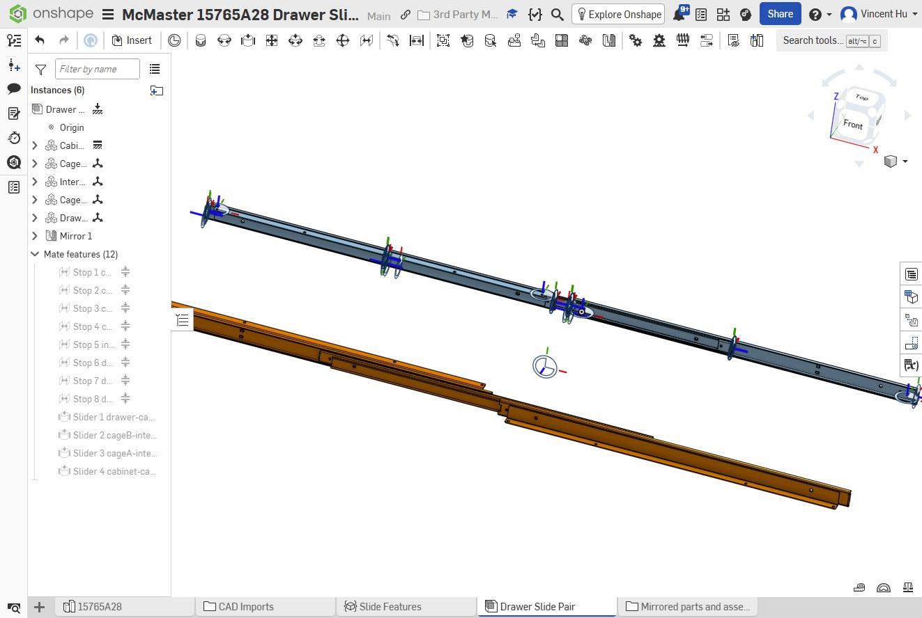
End state of the take: the original slide and its mirrored twin, with 21 connectors visible, twelve mates solved, and V1 created. These will become the pull-out mechanisms in the cabinet shown at the beginning of the video.
The second take was twice as fast because the first take's failures became rules
Here is the honest accounting. Take 5 spent seventeen of its thirty-eight minutes in two debugging holes. Nine minutes went into four blind revisions of a feature whose loop worked correctly in both the evaluator and the sandbox. The useful error—getProperty: Cannot get properties during feature regeneration—had been visible in the Feature Studio notices panel the entire time. Another eight minutes went into diagnosing the twelve overdefined mates. That evening, I added both fixes and the stop-face rule to the workflow recipe and skill files.
Take 6 inherited those lessons instead of rediscovering them.
| Take 5 | Take 6 | |
|---|---|---|
| On camera | ≈ 38 min | 16 min 26 s |
| Feature errors | 1, through 4 code variants | 0 |
| Mate errors | 12 | 0 |
| Stop connectors | 10, on box extremes — rejected | 14, on stop faces, matching the reference to 0.01 mm |
| Onshape MCP API calls | 33 | 2 |
| Corrections on camera | 5 | 1 (a menu, not the model) |
Where the 38 minutes went, and what was left of them once the failures had been converted into written rules.
The comparison is not perfectly controlled: Take 6 benefited from code written during the earlier attempt, and its one visible failure—the unresponsive submenu—still cost two minutes. That failure ultimately produced a better proof. More importantly, the two debugging problems that dominated Take 5 were not avoided by luck. Five explicit rules prevented them: read the notices panel before changing code; send open limit sides as isNull: true on every write; place stop connectors on faces, never bounding boxes; create the stops before the Slider mates; and read the pose from the assembly definition instead of inferring it.
The rule survives the run
The enduring value of the agentic workflow is not the successful run. It is the understanding of the design intent of the drawer slide mechanism. The agent now understands the physical implications of tabs, stoppers, and locks on the rails, and can carry the insight to all future drawer slide modeling tasks.
That understanding now lives in slide-stop-connectors.fs, the recipe's import section, and the mechanism pattern in the onshape-cad-workflow skill, alongside the smaller lessons paid for by both takes. The next vendor mechanism through this pipeline—whether a rail, hinge, or gas strut—starts with those lessons already in place.
Part 3B places three of these slide pairs into the cabinet shown at the beginning of the video: an 80/20 frame with equal-height pull-out tiers and a 3D printer on the top tray.
Drawer slide: McMaster-Carr 15765A28, hold-closed base-mount, 28". The reference pair used to verify the generated connectors was hand-built in Onshape.